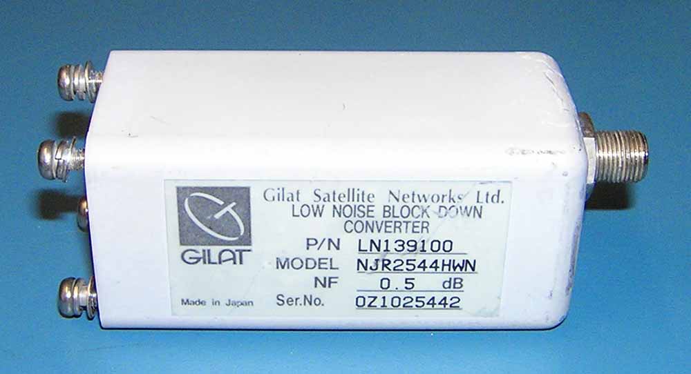
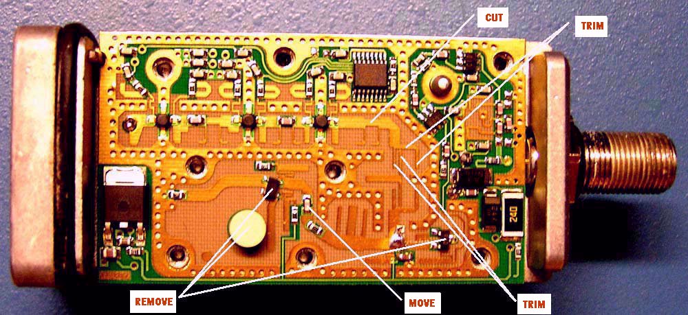
The newest generations of low noise block down converters or LNBs make very good low noise amplifiers (LNAs) if properly modified. The NJR2544HWN works very well, but requires both circuit and hardware modifications. The only components that are needed are the voltage regulator and the three transistor amplifiers. The oscillator, mixer and IF amplifiers are not required and must be removed or disconnected. The F connector on the LNB carried voltage and the IF output.
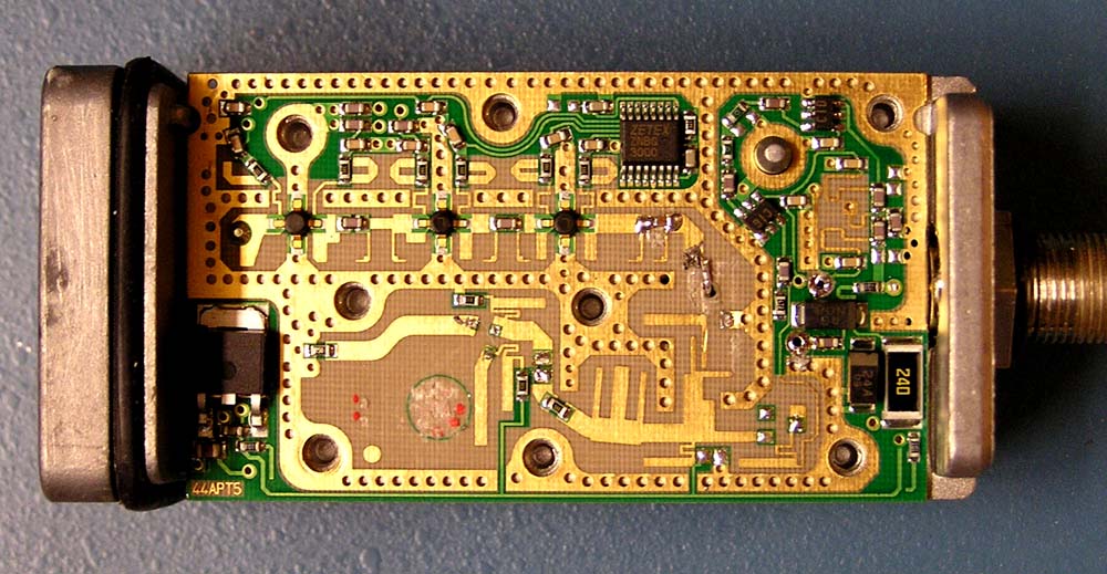
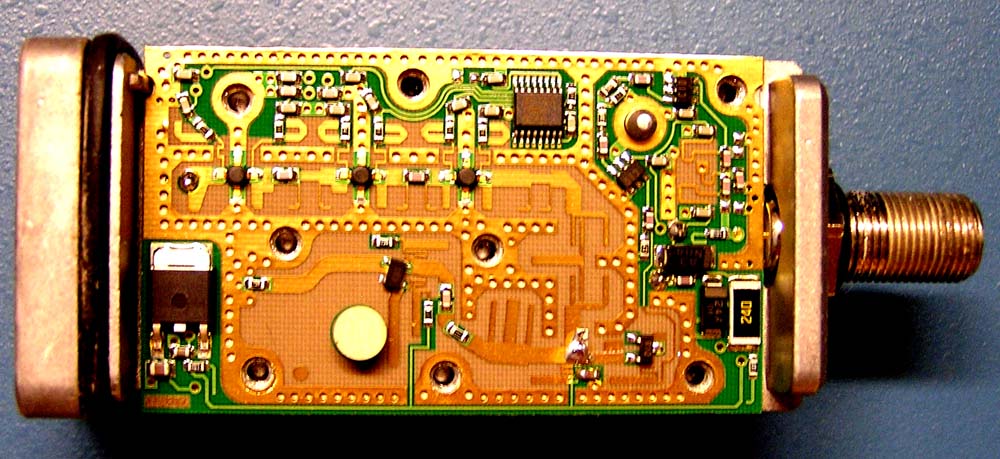
As seen in the second photo, the regulator is in the lower left corner of the PC board. The three amplifiers are across the top and the oscillator is the white puck beside the regulator. The IF circuitry is in the upper right side.
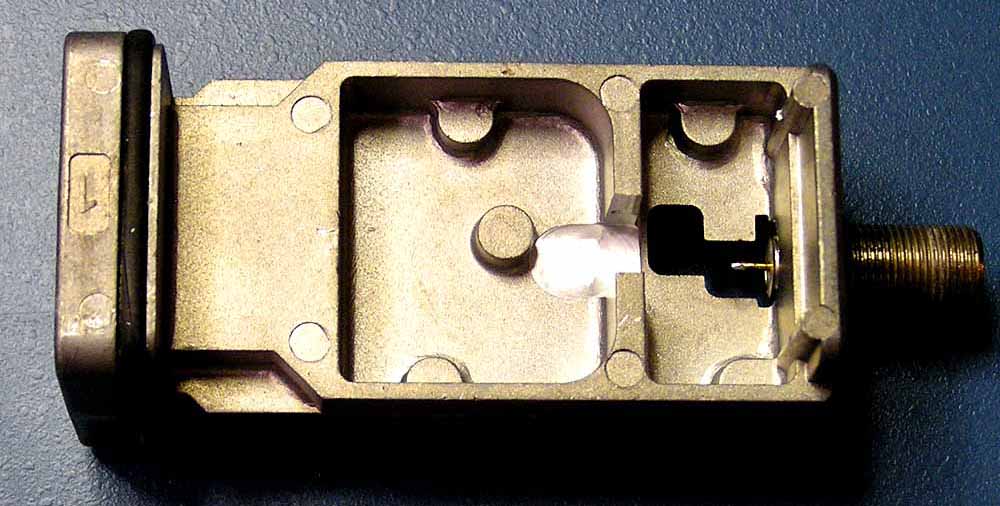
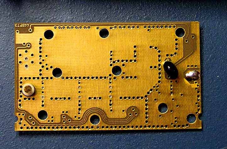
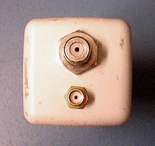
The underside of the unit has a hole to solder the F connector pin to the PC board.

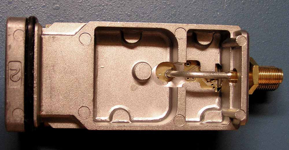
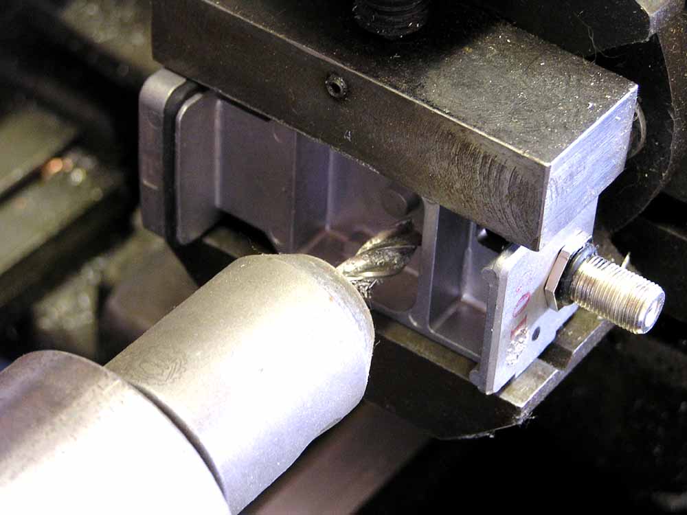
The PC board is only held on by being soldered to the F connector. Once unsoldered, the casting can be modified. A short piece of coax with a bulkhead connector needs to be attached to the the PC board near the output of the last amplifier transistor. There is a partition across the underside of the the casting that will block any coax to the outside. The casting is placed in the mill and a slot that is even with the floor of the cavity is removed. A .312 cutter was used, but the width isn't critical.
The Oscillator and mixer are removed and the traces between the last amplifier stage and the mixer are modified with a dental scraper. Only the trace that curves toward the middle of the PC board remains. The end of this trace is the attachment point for the output coax.
Before the trace curves, there is an area of trace with two "L" shapes on either side of a narrower trace. As this trace has voltage on it, the voltage needs to be blocked. There is a chip capacitor near the oscillator. After the narrower length of trace has been removed, the chip capacitor must be relocated to bridge the gap.
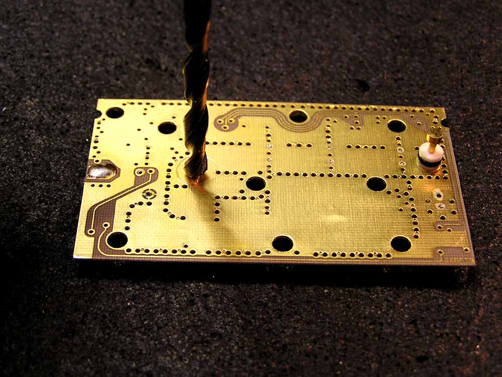
With the PC board placed onto the casting, a small, sharp center punch or strong probe is forced through the fiberglass board with enough force as to mark the casting. This will be the location of the coax termination and is in the center of the board about .10 inch below the end of the trace. With the board removed, a .25 hole is drilled through the casting.
With the casting inserted into the case, a .25 hole is drilled through the case and casting at one time. The hole is located below the F connector. This hole will allow the coax to be installed.
The coax hole that was pushed through the board, comes out the under-side that is ground. The ground material must be removed so as not to short out the coax. This can be done by twisting a small drill (.125) with your fingers until the material is removed. The area around this hole is lighly tinned with solder to allow the coax shield to be attached.
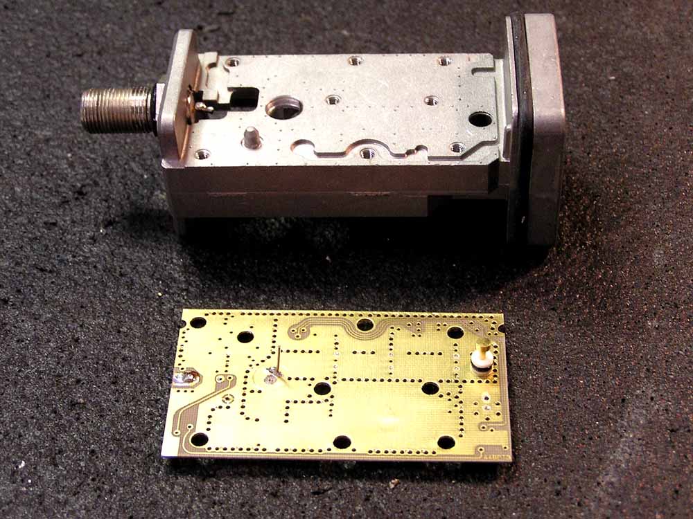
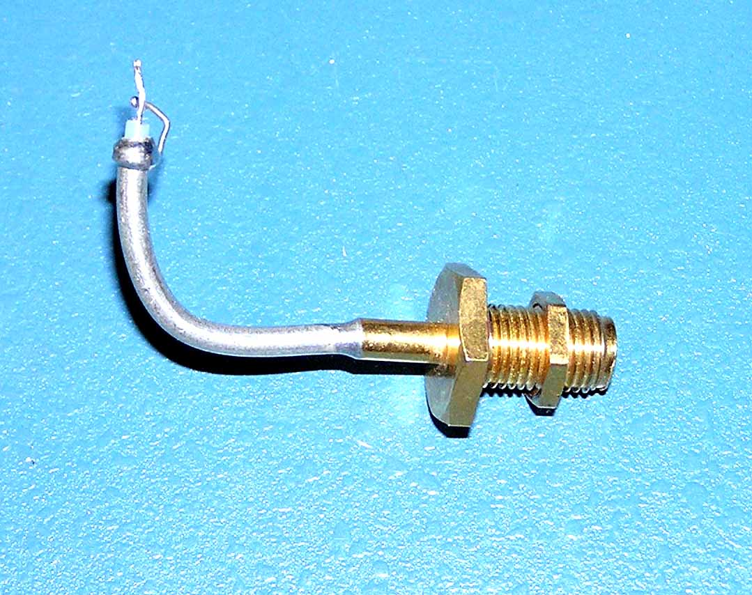
The coax is prepared and bent as shown to fit through the casting holes. The PC board is soldered to the F connector and the coax is installed. There should be enough room to tack the shield wire to the tinned area beside the coax's center pin hole. The coax center wire is bent over and soldered to the end of the trace.
The shell is fit over the casting and the nuts are tightened on the SMA and F connectors. The unit is ready for testing once a WR75 transition has been provided. A suitable transition is described here. The voltage input through the F connector can be between 12 and 28 VDC as it only needs to power the 5 volt regulator.