Commercially made waveguide to coax transitions are usually designed for broadband testing. For communication work, the transitions should be tuned. This tuning may be to optimize gain (best return loss or impedance match) or noise figure (NF). The match point for best gain and noise figure are often not the same. Gain (return loss) tuning may be done with a signal generator, spectrum analyzer and a directional coupler. With a signal applied to the transition, which has been coupled through a directional coupler and a termination, the return loss is monitored and the tuning adjusted for best SWR. This same procedure is used to optimize the tuning of an antenna input. The positioning procedure for the adjusting screws is the same.
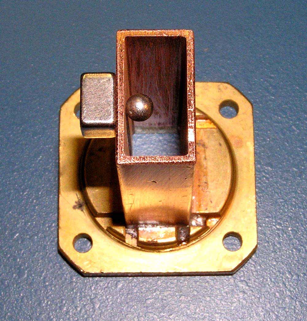
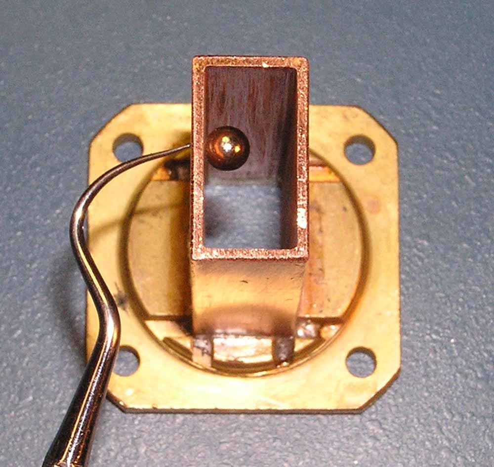
While monitoring the display, a steel BB shot in dropped into the waveguide and moved around with a magnet (first images) until a "hot spot" is found where the return loss is minimum. The BB is removed and the screw (usually a #4-40 brass) is placed in the hot position. Minimum return loss will usually take 2 screws. If you can get a BB sized magnet the procedure will be more accurate and the magnet (second images) can be manipulated with a sharp dental tool. The dental tool can scribe the hot position.
If you are making a transition for use with an LNA, then a noise figure meter is needed for best results. The BB or magnet can be positioned for best NF as indicated on the meter and replaced with a screw. One screw seems to be adequate for the best NF. It isn't in the same position as one located for best gain.
The length of the transition isn't critical, but enough length is necessary to locate the "hot spots". This transition is 2 inches overall. After a scrap of .50 brass is soldered to the end, it is trimmed with a nibbling tool and finished with a file.
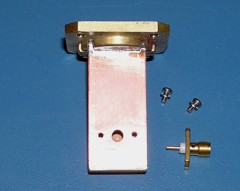
The SMA connector is placed in the center of the waveguide, .45 inch from the inside of the end plate. This insulation is trimmed to the width of the waveguide wall and the center pin is trimmed to give .20 inch of exposed length inside the waveguide. Number 2-56 screws are placed in tapped holes to hold the SMA. If necessary, the screws are shortened so they don't extend into the waveguide.
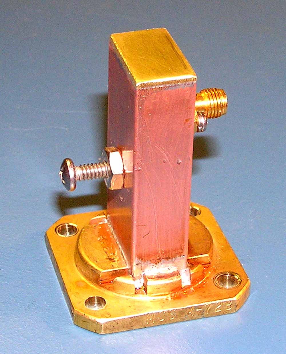
A single #6-32 brass screw was used with a brass back up nut to tune the transition for best NF. Additional improvement may be made by cutting the probe length a bit long and slowly shortening it while monitoring the NF meter.
Measurements were taken as this transition was made and compared to other transitions both for gain and best NF. The NF measurements are not highly calibrated, but are useful for comparison. The following tests were made with the same LNA with a WR75 input flange at 10375 GHz.
The untuned transition resulted in a gain of 24.4 dB and a NF of 2 dB.
A transition tuned for best gain (2 screw) had a gain of 30 dB and a NF of 1.1 dB.
The transition tuned for best NF (1 screw) had a gain of 29 dB and a NF of .8 dB.