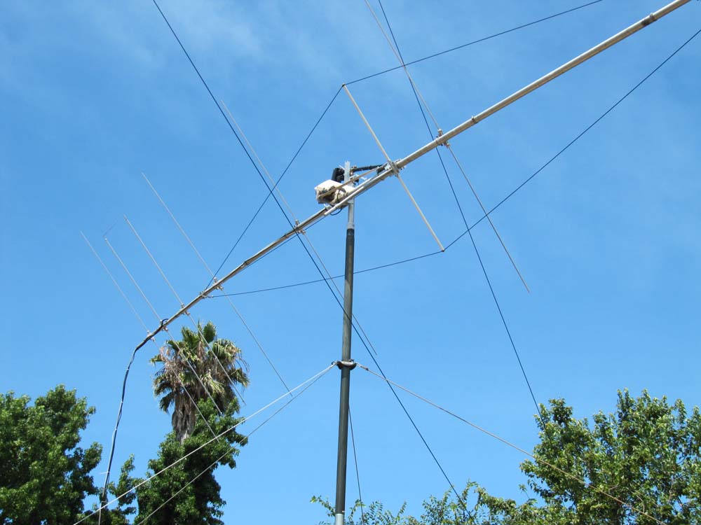
The LFA was doing a good job, but when I was being heard well in Europe, I wasn't hearing them. Faraday rotation was being blamed for this. I proceeded to build an enhanced version of the LFA with full remote controlled rotation of the boom. After several mistakes, I was able to make it work. The basic antenna was never modified except for the routing of the coax and control cables.
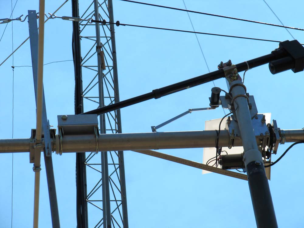
In a horizontal antenna the cables and support structures including the mast are at right angles to the elements and don't affect the performance. When you rotate the boom into vertical, the mast and cables are in the near field. My fix was to route the cables off the back end of the boom and to add side guying to the boom using .75 fiberglass rod and Phillystran cable. I also added a counterweight opposite the aluminum vertical support.
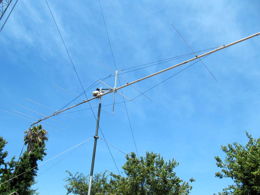
The top 2 sections of mast tube were replaced by fiberglass. No interaction was noticed in testing.
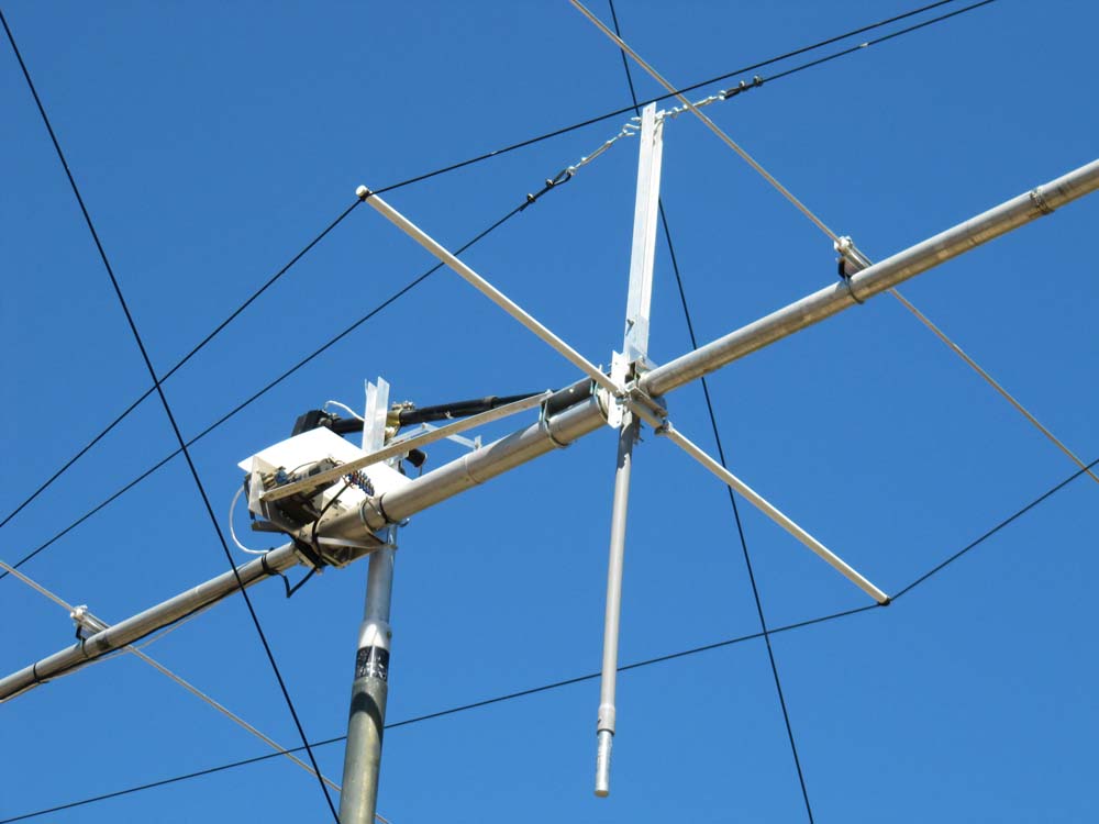
With the easy parts completed, the rotation mechanism was started. Between the center of gravity point on the boom to the clamps holding the vertical support there is about 2 feet. The boom at this point is 2 inches in diameter. I bought a piece of 2.5 inch diameter heavy wall tubing made from 6061 T6 aluminum. The clearance between the OD of the boom and the ID of the larger tube was about .180. Short pieces of the larger tube were put into the lathe and the ID was enlarged about .010 so that a clearance of slightly larger than .188 was available for a bearing.
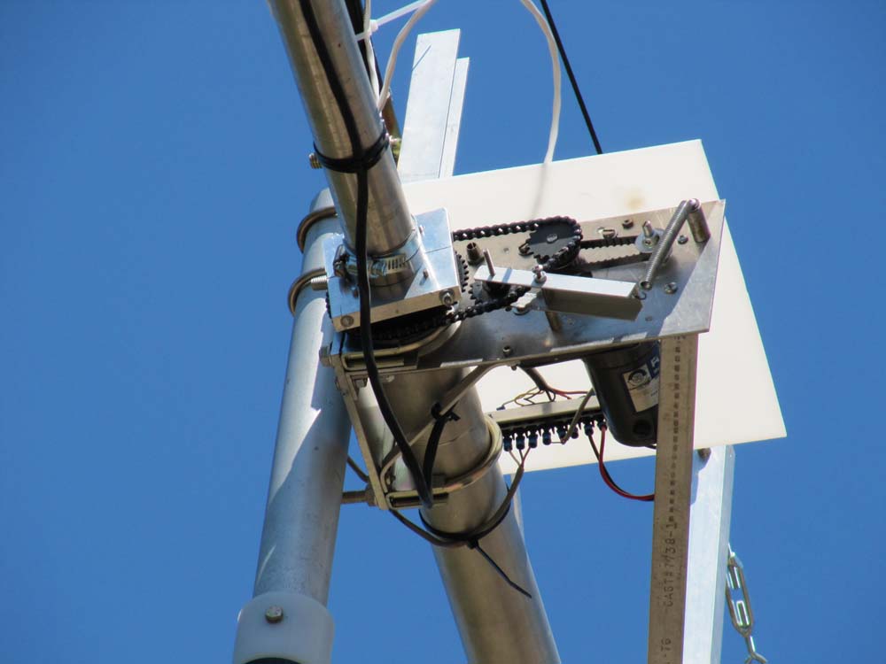
Placing twenty .188 and twenty .156 by 1 inch rods between the boom and the larger tube made the bearings. If you put all .188 rods in the bearing, each rod would rub the adjacent rod because where they touch, they are going in opposite directions. The smaller rods act as idlers and help transfer rotation. The rods are prevented from moving by coupling sleeves made of UHMW (Ultra-High-Molecular-Weight Polyethylene) that couple the bearing ends to the main tube. They also make a good place to do heavy clamping to keep the structure from moving. A PVC coupling was enlarged to make the end-stops. The boom now rotated with little effort. As the larger tube doesn't move, the vertical positioner and its potentiometer must be clamped to it. To keep the assembly from moving during high vertical operation, two plastic washers were made to take the load from the support clamp.
After many failures, a suitable motor was found. It is a 90-volt DC motor with gear reduction that came from an old photo dryer and would operate at a slower speed with reduced voltage. A clamp to grip the boom was made from a piece of 3.5 X 3.5 X .50 aluminum. The plate was drilled in the center with a 2-inch hole and then cut in half to make an adjustable clamp held together with two long screws. A 4-inch chain sprocket had its bore drilled out to over 2 inches and attached to the clamp with 4 screws and spacers. Number 25 chain was run to the driver sprocket on the motor. An idler sprocket was added to keep tension. The rotation position is measured by a three-turn potentiometer that is also driven off the motor but with a small timing belt. A length of rotor control cable carries the voltages for the motor and the rotation and vertical position potentiometers (8 wires).
The control for the rotation is done in a salvaged CDE rotor box. To get the required voltage (about 40 VDC), a small transformer was wound. The rotor box has a SPDT set of contacts on the spring-loaded switch, so only 2 wires could go to the motor. The AC from the transformer is fed to 2 power diodes and their filter capacitors. One diode is positive and the other negative with a common ground.