I have always wanted to try EME on any band, but especially on 6 meters where I was trying to make 100 countries. A new type of yagi has been developed by G0KSC called the LFA or Loop Fed Array. This antenna is reported as being lower noise than conventional yagis and had a very low SWR for 500 KHz, so I started assembling parts. W6QUV offered to give me the 32 foot boom off an old antenna, so the hard part was done.
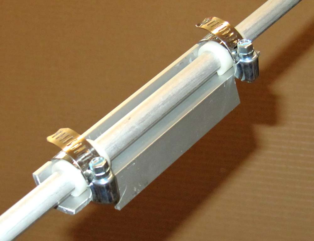
The element to boom clamps were made from some "Z" extrusion that was noched on the ends to allow hose clamps. Plastic insulators were made on the lathe and split to allow tightening on the .50 and .375 inch diameter elements. The reflector and all the directors were made of .375 inch aluminum tubing that were joined in the middle with a 6 inch piece of .25 tubing that was pop rivited in place. Standard 2 inch antenna clamps were used to attach to the boom.
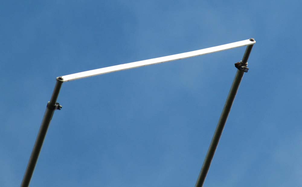
The driven element is a horizontal loop attached at 2 points to the boom and fed at the rear position. The loop is made of .50 tubing with the 2 connections on the ends being made of .50 flat stock with .375 solid rod extending into the element ends. Six inches of tapped rod were used to allow for adjustment. This construction guarantees that the loop is symetrical and is easy to build. Trying to bend tubing in a nightmare and this construction is closer to the computer model.
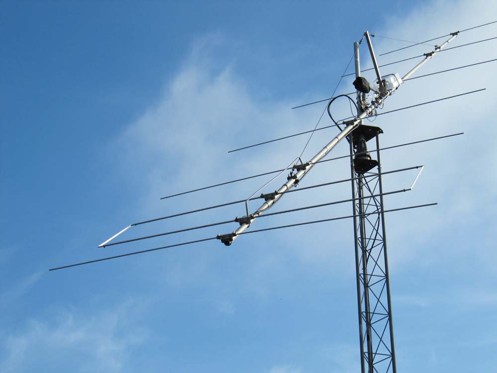
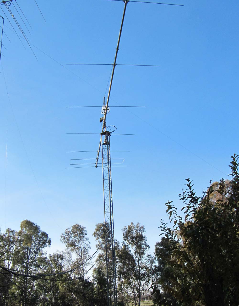
When noise in the city became too much, we moved into the country to an old farm. The LFA was assembled on its military mast where it quickly made enough QSOs for DXCC on 6 meters. With more room I could now aim in all directions, but needed to get a little higher. Three sections of Rohn 25G was placed in a yard of concrete to make a 25 foot, free standing, tower. Azmuth is controlled with a Yaesu G-800 rotor.
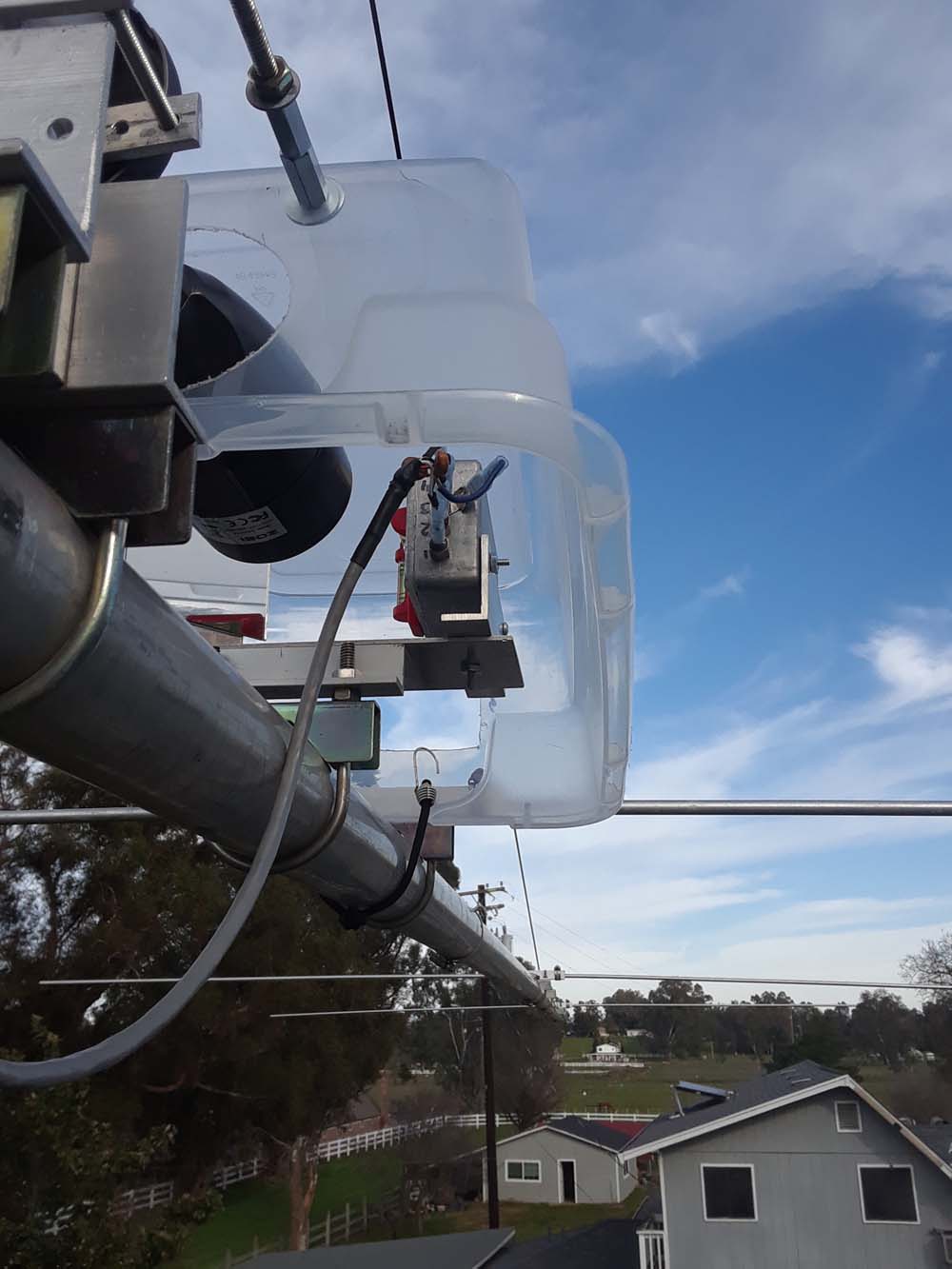
The antenna has up to 60 degrees of elevation. The mast plate holds the actuator and the boom plate hangs on a pivot pin.
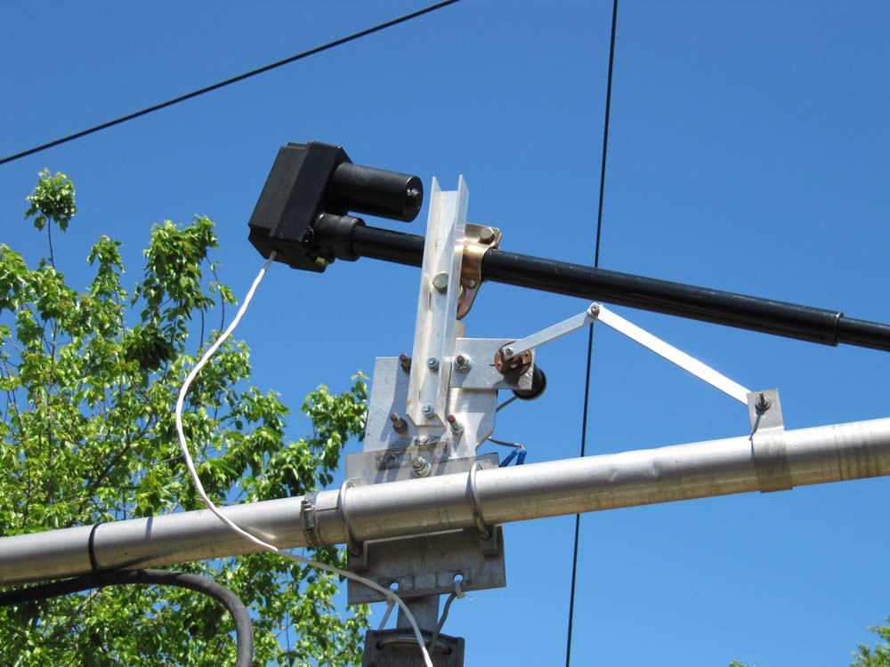
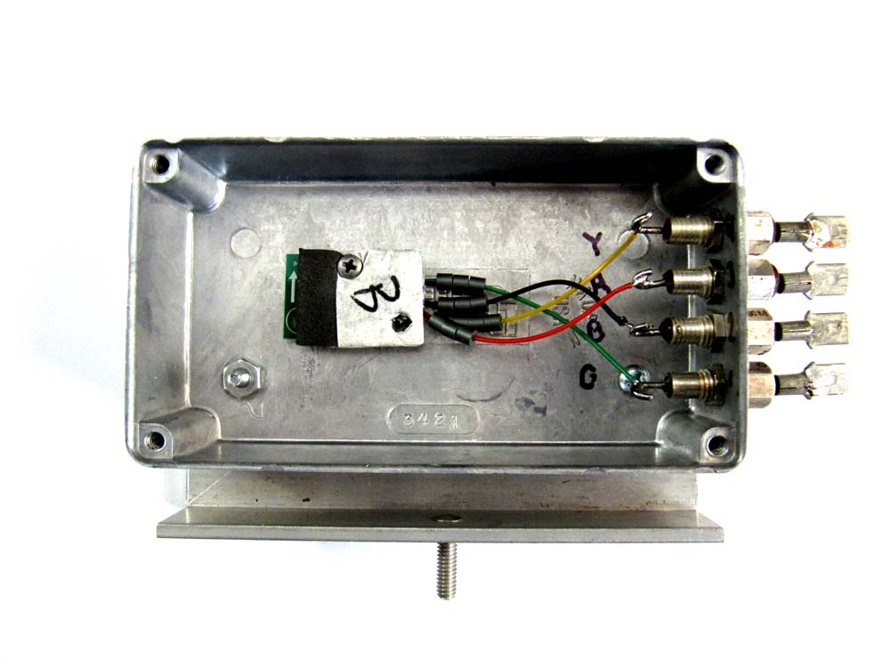
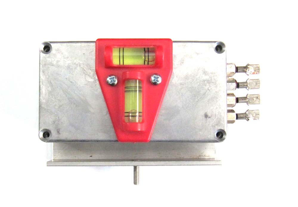
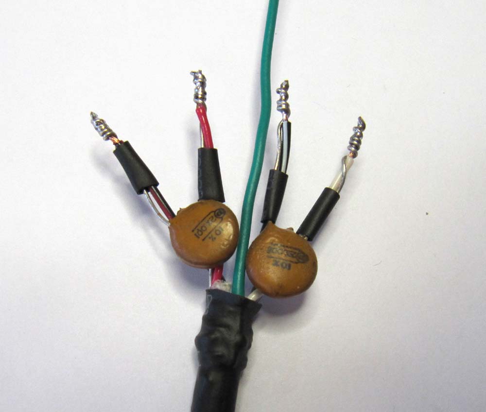
I mounted an inexpensive closed circuit camera so I could sight down the boom. That worked great until I tried it during the day or when it was cloudy. A vertical angle readout was modified from a digital level. The angle sensor was removed from the level and mounted inside a shielded box. A four conductor shielded cable runs about 100 feet back into the shack where the display on the level has been remounted. The display is powered by a 3 pin regulator that supplies 3 volts DC instead of some batteries. The shielded cable has its conductors bypassed and enters the sensor box and the shack through bypass feed through capacitors. High RF was a problem, so the shielding is necessary. (I blew the first unit up!) The bubble level and mirror allow me to do a sanity check on the display when the antenna is level.
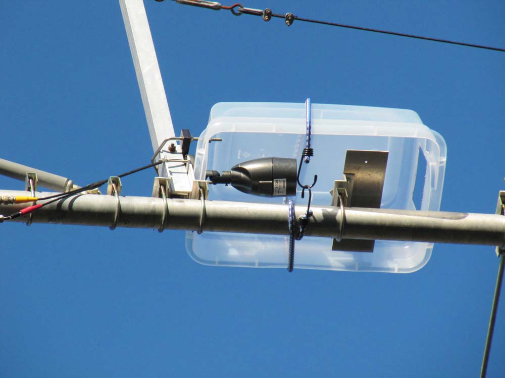
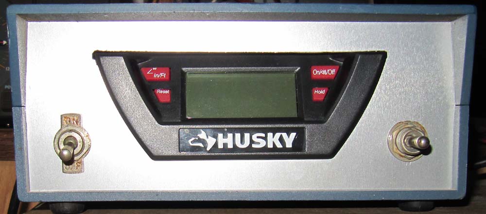
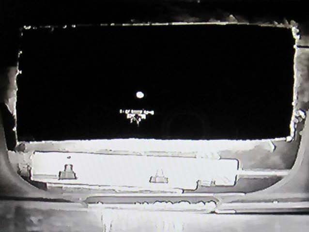
Now all I need to do is aim at the moon when it's visible or rely on the rotator for azmuth and digital readout for elevation. The shape in the middle of the rectangular view hole is the driven element bracket. The moon is centered above the bracket about 2 inches up. It all seems to be working and I now have a total of 125 countries on 6 meters. The low antenna also works very good on e-skip into Europe in the Summer.
Description for the modification of the level to make the elevation display is here.
Complete dimensions with conversion to inches is here.