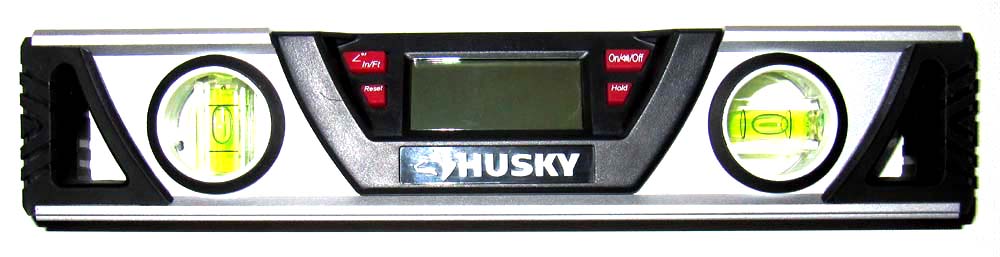
The methods I have tried to remotely read the elevation angle of the EME yagi, have not worked out. There are several devices like carpenter's levels that are made for a digital display. NJ6P and others have been working on remoting the display from the angle sensor. I decided to give it a try. The 10 inch "HUSKY" level was purchased from Home Depot for about $40.
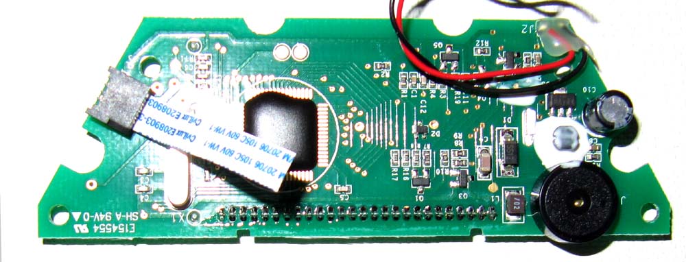
The cable is attached to the display with a connector that needs to be carefully unsoldered.
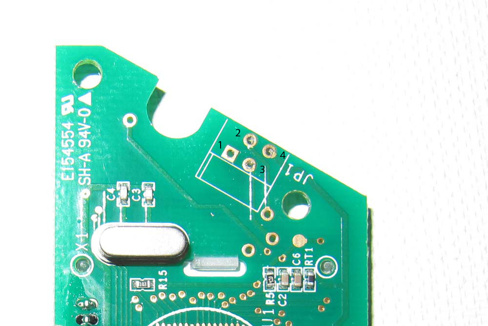
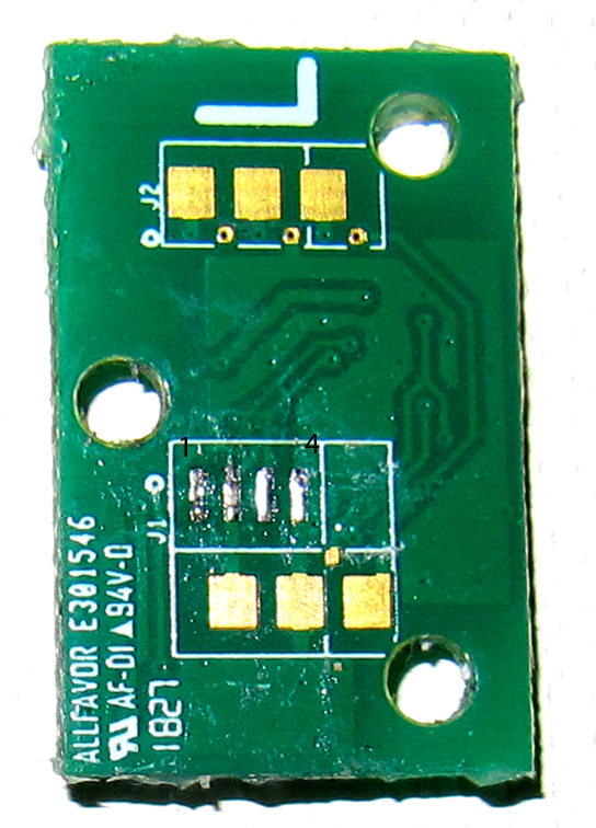
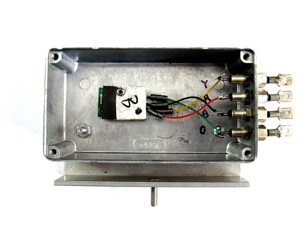
The cable attaches to the sensor on the back. The cable may be completely removed or cut off close to the board. You can solder directly to the pads either way. I color coded the new wires and made a chart to keep things wired correctly. The sensor is wrapped in "masking" tape that can be carefully cut off to expose the connections. As you look at the board from the ribbon cable end, the left tab will be #1 and the other 3 are in order. See the numbering below.
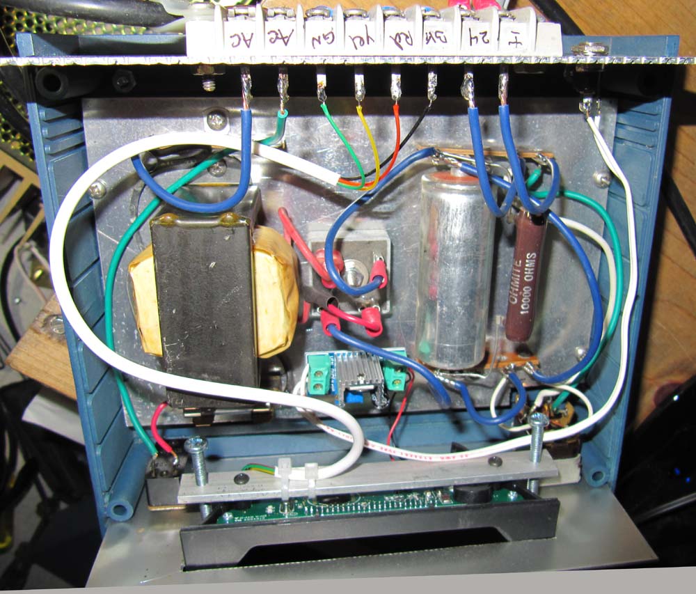
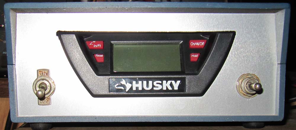
The display was mounted in a project enclosure from my junk box. A very odd shaped hole to fit the display was nibbled out of the panel. A small flat piece of amuminum was drilled to match the threaded holes in the back of the display. A pair of #8 threaded holes were drilled and tapped on the ends of the aluminum to allow the display to be held in place. A small PC board holds a 3-pin regulator circuit that provides the 3 volts DC to power the unit. The source voltage for the regulator comes from an external 12 volt regulated supply. The 35 Volt DC power supply is used to supply voltage to operate the elevation positioner. The toggle switch on the left turns the power supply on. The switch on the right is an "ON-OFF-ON" type to move the positioner up and down,
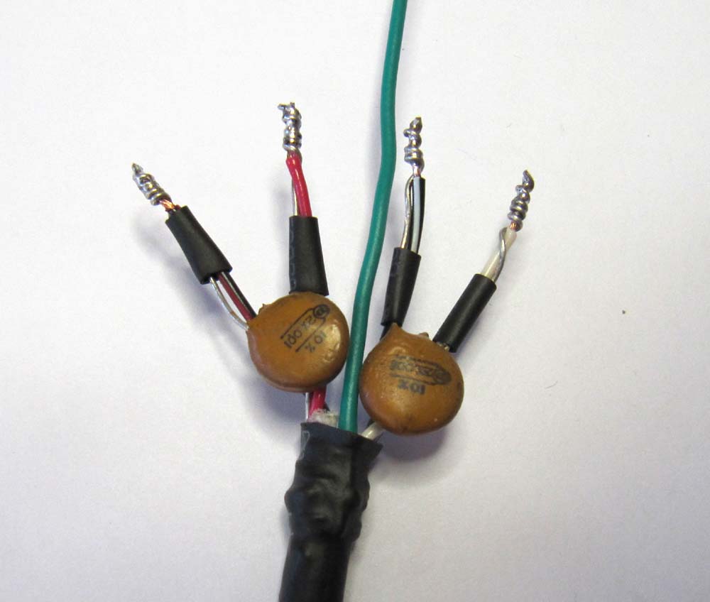
When the equipment was installed on the antenna, I transmitted with the 1500 watts that had distroyed the first sensor. No problem at all. I was not willing to blow another $40 to test each shielding method at a time and recommend you use all the shielding you can.
The remaining level frame has excellent magnets on the bottom that will clamp to a tower leg when setting guy wires. Not a wasted tool.