The construction of the box was the same as the push pull amps. Two sheets of .06 thick aluminum were cut to the size of the final front panel. The two sheets were laminated together using "J-B Weld", a two part epoxy. The studs were placed in the inside sheet. The final sheet was laminated over the stud heads and was easy to paint over. The socket is made from a sheet of aluminum turned to a circle on the lathe. Air holes are added inside an HDPE ring cut to hold the glass chimney in position. The chimney is held down with a length of high temperature foam rubber held in place with a hose clamp. The anode connection is made with a large screw into the top of the radiator that has been drilled and tapped to take a #10-32 brass screw.
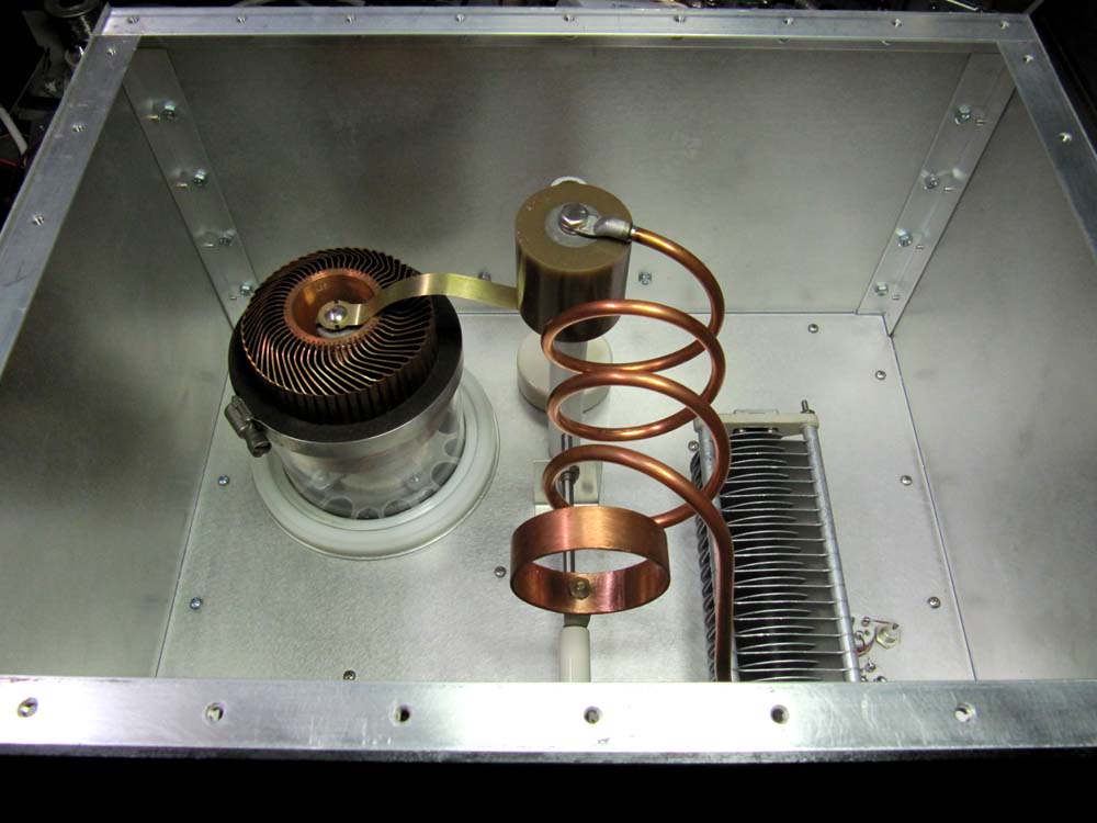
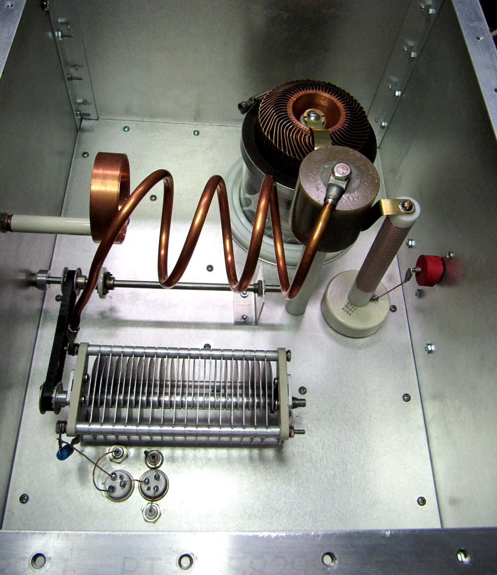
The circuit is the PI network with a "Q" of about 12. The 7 uh RF plate choke was wound on .75 inch diameter Delrin rod that was threaded to space the #22 wire. The choke sits on a by-pass capacitor and is fed voltage through a high-voltage feed through capacitor (6 KV). Input and output relays are RJ1A Jennings vacuums. A variable capacitor of 150 pf provides the loading. A Z-50 inductor is used across the loading capacitor for protection. Plate tuning is done with a closed turn near the cold end of the .25 diameter copper tubing plate coil. At 6 meters, the desired tuning capacity is already high due to the tubes output capacity and circuit strays. Using a variable capacitor with its minimum capacity, would make the circuit Q too high and therefore lossy.
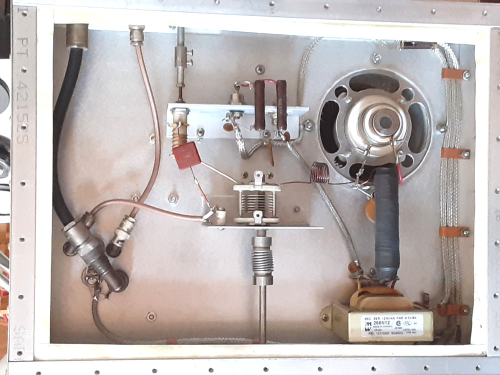
The filament choke is wound on a .50 diameter ferrite rod. The bias is high for the GS-35B, so a pair of 20 volt, 50 watt, stud mounted zeners are used (1N3319B). At 40 volts of bias, the idling current is 180 ma. The zeners are connected to the filament transformer center tap. This amp is designed to run nearly 4000 volts. If around 3000 volts is to be used, 16 volt zeners may be used. All leads are filtered with an RF choke and feed through by-pass capacitor. A thermistor (CL-60) is placed in a filament transformer primary lead to cut the inrush current. The voltage to the filament transformer is also fed through a micro-switch with a wind vane to turn the tube off if the air supply fails. The air enters the amplifier through a honeycomb duct.
A "T" match is used to tune the input and is adjustable from the front panel. The input inductor is 6 turns on a 1/2 inch slug tuned form. The output coil is 6 turns of #18 wire that is 5/8 diameter and is 3/4 inch long. The variable capacitor is 50 pf.
Testing is done with a carbon resistor of 2950 ohms tied from the tube's anode to ground to similate the load impedance. The plate circuit is tuned for 1 to 1 SWR using an impedance bridge (MFJ-269). A 35 ohm carbon resistor is tied from the cathode to ground to test the "T" match.
With 3800 volts at 700 ma on the plate, the output is 1500 watts. It requires about 80 watts of drive.
BACK TO CONSTRUCTION PROJECTS
HOME
The circuit is the PI network with a "Q" of about 12. The 7 uh RF plate choke was wound on .75 inch diameter Delrin rod that was threaded to space the #22 wire. The choke sits on a by-pass capacitor and is fed voltage through a high-voltage feed through capacitor (6 KV). Input and output relays are RJ1A Jennings vacuums. A variable capacitor of 150 pf provides the loading. A Z-50 inductor is used across the loading capacitor for protection. Plate tuning is done with a closed turn near the cold end of the .25 diameter copper tubing plate coil. At 6 meters, the desired tuning capacity is already high due to the tubes output capacity and circuit strays. Using a variable capacitor with its minimum capacity, would make the circuit Q too high and therefore lossy.
The filament choke is wound on a .50 diameter ferrite rod. The bias is high for the GS-35B, so a pair of 20 volt, 50 watt, stud mounted zeners are used (1N3319B). At 40 volts of bias, the idling current is 180 ma. The zeners are connected to the filament transformer center tap. This amp is designed to run nearly 4000 volts. If around 3000 volts is to be used, 16 volt zeners may be used. All leads are filtered with an RF choke and feed through by-pass capacitor. A thermistor (CL-60) is placed in a filament transformer primary lead to cut the inrush current. The voltage to the filament transformer is also fed through a micro-switch with a wind vane to turn the tube off if the air supply fails. The air enters the amplifier through a honeycomb duct.
A "T" match is used to tune the input and is adjustable from the front panel. The input inductor is 6 turns on a 1/2 inch slug tuned form. The output coil is 6 turns of #18 wire that is 5/8 diameter and is 3/4 inch long. The variable capacitor is 50 pf.
Testing is done with a carbon resistor of 2950 ohms tied from the tube's anode to ground to similate the load impedance. The plate circuit is tuned for 1 to 1 SWR using an impedance bridge (MFJ-269). A 35 ohm carbon resistor is tied from the cathode to ground to test the "T" match.
With 3800 volts at 700 ma on the plate, the output is 1500 watts. It requires about 80 watts of drive.