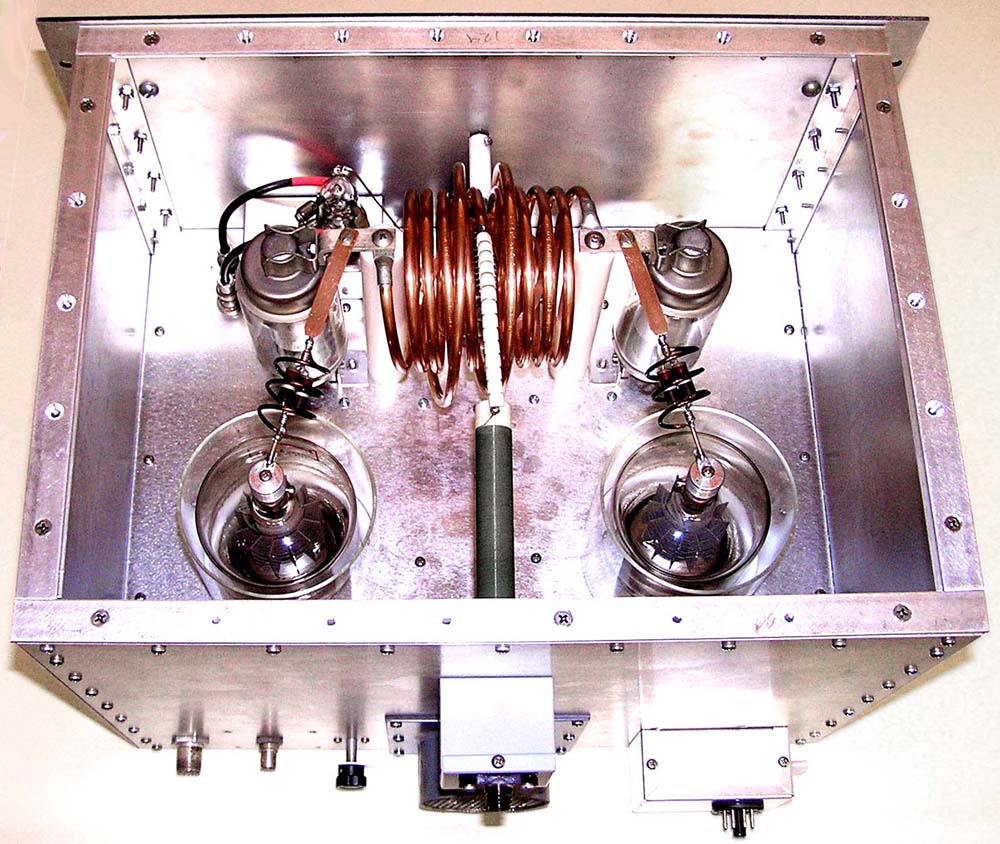
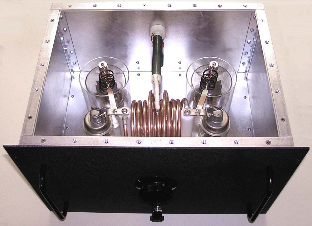
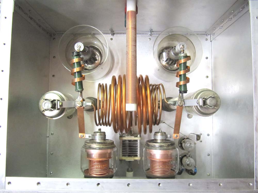
After building many amplifiers since 1960, I was never satisfied with the performance or durability of my equipment. I had built a 20 meter, push pull, amplifier using 4-400A tubes that worked well but was always a bit unstable during tune ups. I had never seen a grounded grid, push pull amplifier before, but knew it could be built. When I figured out the circuit, I re-wired the 20 meter amplifier and it worked perfectly. New amplifiers were built over the next 2 years for 40, 17, 15, 12, 10 and 6 meters. The following photos are of the 6 meter amplifier which uses 3-500Z tubes and followed by the 20 meter amplifier that uses 4-400A tubes.
Push pull was chosen for the single band amplifiers because all my tubes were used and nothing matched. In push pull you don't need matched tubes, harmonics are minimized and they are more efficient at higher frequencies as the circuit capacity is less and the circuit "Q" can be optimized.
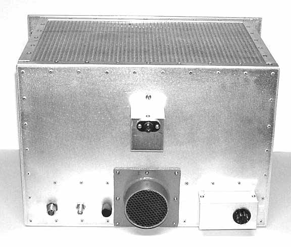
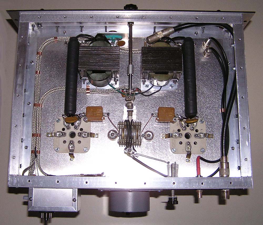
A common power supply is used on all amplifiers, so there is no need for duplicate metering. The enclosures are made with a frame of aluminum angle that aluminum panels are attached. No more that 2 inches between fasteners is used to minimize RF leakage. The air is brought through a duct in the rear with honeycomb RFI material inserted in the opening. All wiring enters through a box in the corner where it is wired to feed through capacitors. All wires are filtered as they enter the enclosure including the high voltage.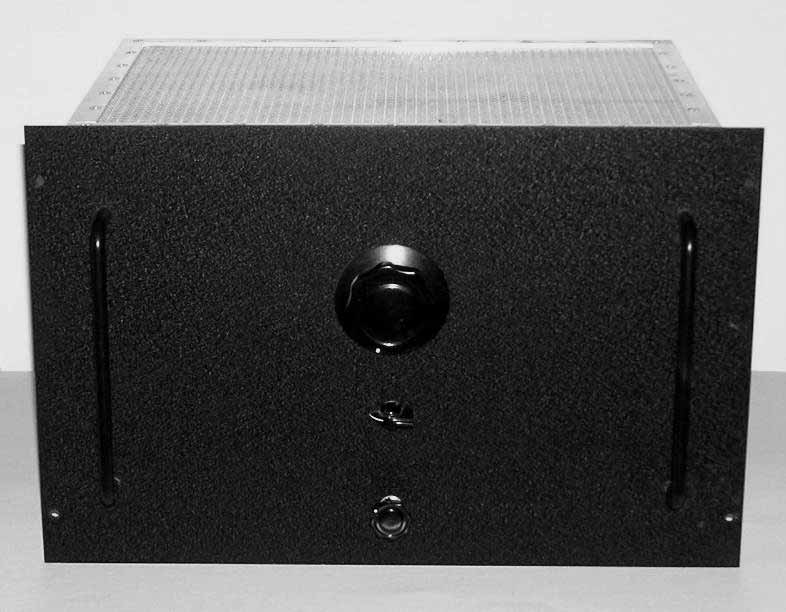
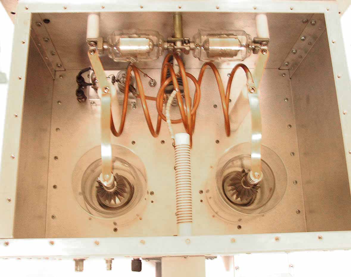
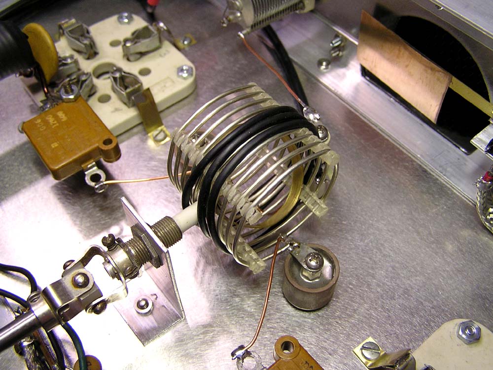
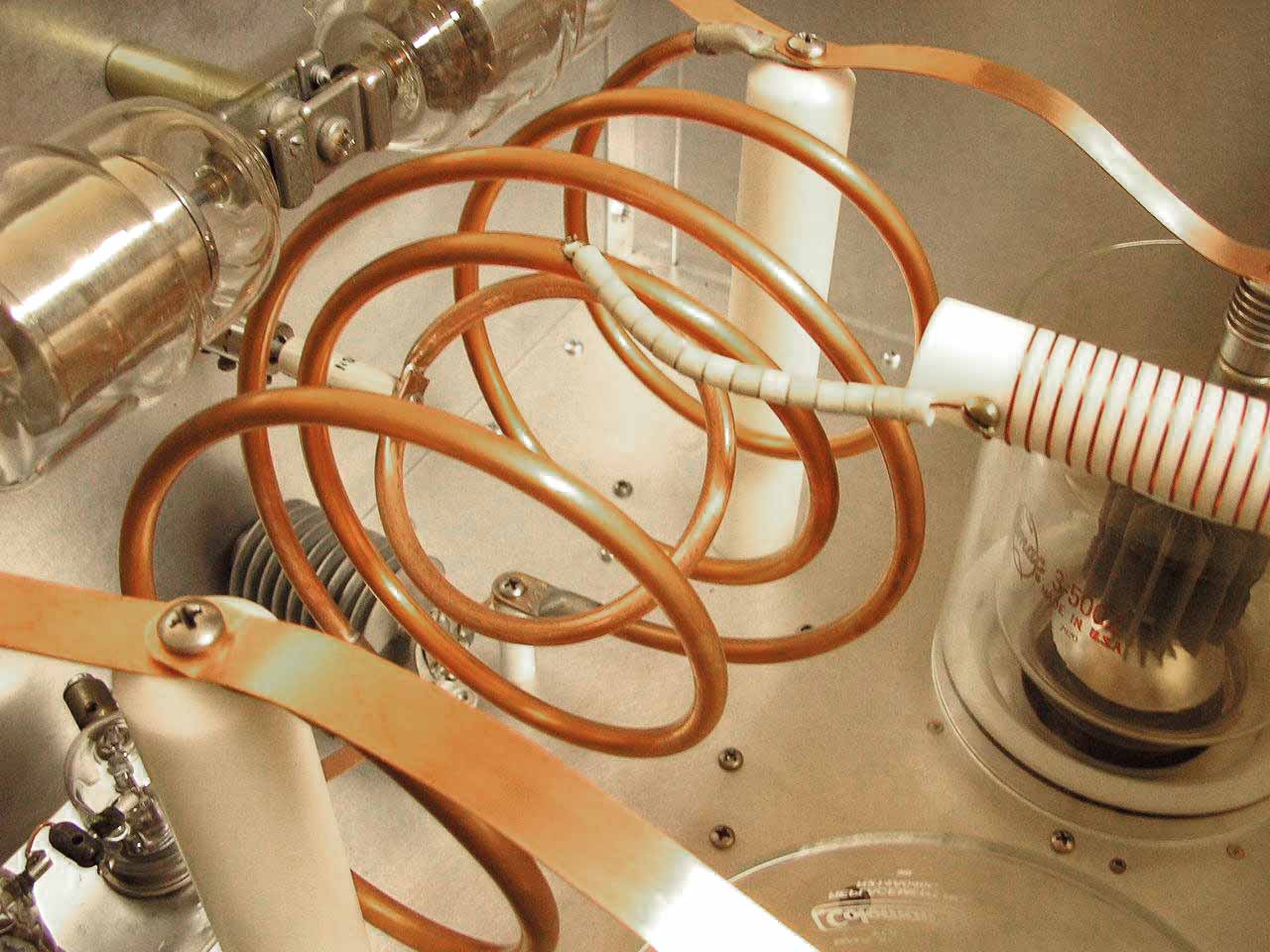
Circuit symetery is maintained where ever possible. The tank coil is .25 copper tubing and it is tuned by a variable link. Tank capacitors are fixed vacuum capacitors. The glass chimneys are "Coleman" lantern glass that is held in place with plastic rings equipped with "O" rings to hold them in place.
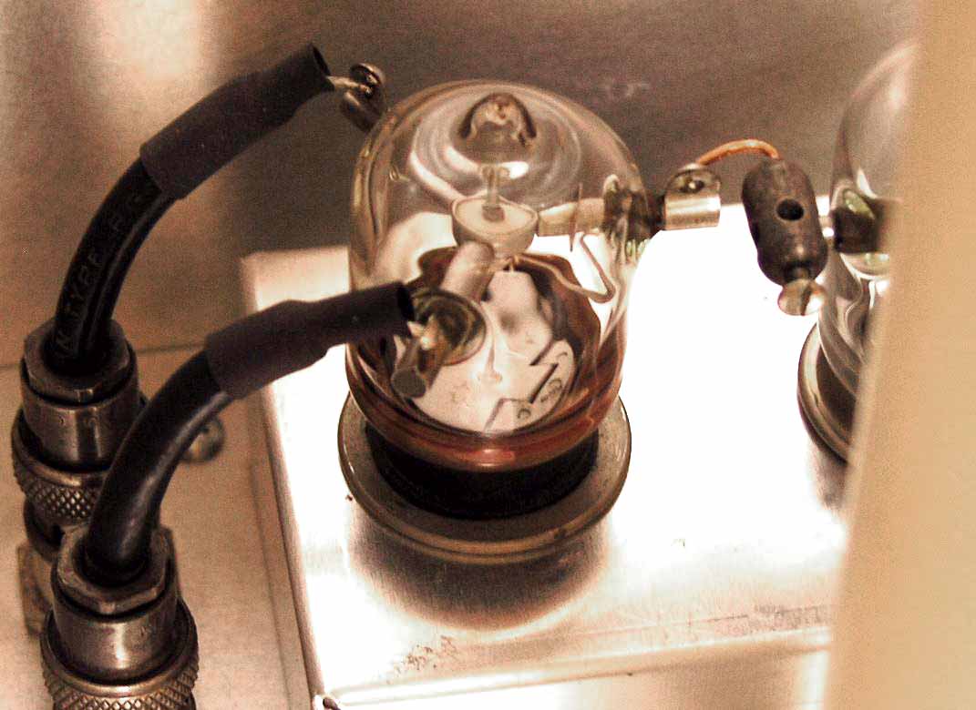
Vacuum relays are used for input and output of power. Two SPDT Jennings relays are mounted near the output link tuning. Coax from the exciter and to the input circuit are brought through the chassis. An RF choke made from "Delrin" was made on the lathe by threading the plastic to the desired pitch and length. The bypass is made using the doorknob capacitor and the HV feed through capacitor.

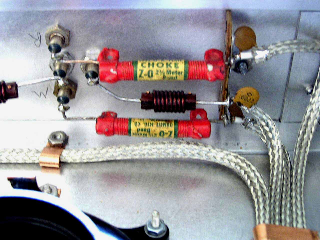
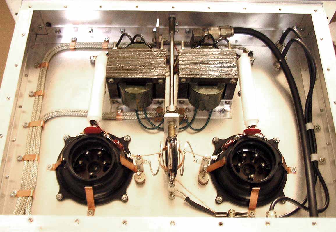
All internal wiring is shielded and grounded at several places. RF chokes help lead filtering as the wires leave the enclosure. Homebrew filament transformers and chokes were made for each tube to maintain isolation. The cathode circuit is tuned by a closed turn and is fed with a tuned link coupling to assure a flat SWR. The grid connections on the tube sockets are grounded by short straps.
The 20 meter amplifier is very similar to the 6 meter amp except it uses the standard 32,000 or 20,000 volt vacuum capacitors.
The 40 meter amplifier uses the same circuit but employs a split stator Eimac vacuum capacitor assembly.
HOME