Many antennas are available that are designed to operate on the 902 MHz amateur band. Very high gains can be achieved with small antennas at this frequency. Using beam antennas for use on the 902/927 repeater band is another issue. Beams are usually designed for maximum gain and F/B ratio and not bandwidth. When the use of 3 db whips over long distances proved inadequate, a new antenna was tried.
In 1977, N6NB designed the Quagi antenna and it has been made for all the VHF/UHF bands including 1296 with good results. It was usually optomised for maximum gain. On the Internet, I found the design for a 10 element, 900 MHz quagi. This antenna was built and showed better performance than the whip. The dimensions were somewhat suspect, so a 1296 quagi from the ARRL Antenna Book was scaled for 900 MHz. W6SR took these dimensions and analyzed them on a computer using EZNEC-5. With bandwidth, impedance as well as gain being the objectives, a new set of element lengths, diameters and element spacing for a 6 element quagi was developed. A sweep of the antenna across the band confirmed the computer predicted bandwidth performance. Any changes in the diameters, lengths or spacing will degrade the performance.
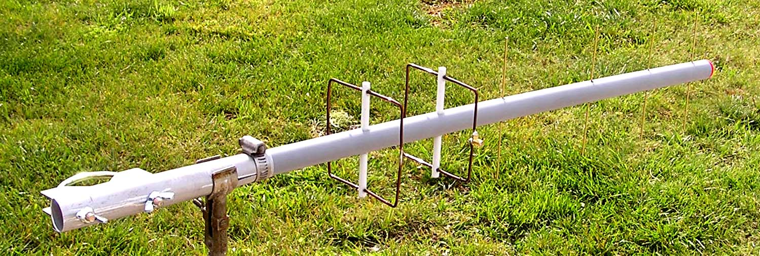
The quad elements were made from #11 AWG copper rewind wire and the directors were made from .063 diameter brass welding rod. The boom was made from 1/2 inch, schedule 40, plastic conduit. This conduit is very cheap and will not degrade in sunlight. The quad supports were made from two, 4 inch lengths of 1/4 inch diameter fiberglass rod. An extra 6 inches of pipe was added behind the reflector for attachment for a total length of 25 inches. I used a 1 inch aluminum pipe to attach to the end with a hose clamp. A small SMA connector was used to terminate the driven element. This termination must be on the side for vertical polarity. The attaching coax should be dressed away at 90 degrees from the element to avoid interaction. Super glue was used to hold the elements in position during assembly and testing. Clear, 2 part epoxy was later used at each element to boom point and also to coat the fiberglass rods for water proofing and the brass directors to stop any corrosion.
The new antennas are noticably better than the original antenna and have a theoretical gain of 9.75 dBd at 920 MHz.

The reflector is placed at the "0" position on the boom and the other elements are spaced as shown on the table from that reference point.
ELEMENT LENGTH SPACING REFLECTOR LOOP 13.88 0 DRIVEN ELEMENT LOOP 13.20 3.36 DIRECTOR 1 5.420 6.50 DIRECTOR 2 5.365 11.40 DIRECTOR 3 5.275 15.00 DIRECTOR 4 5.265 18.00
The SMA connector has the center pin cut to .10 inch. A longer pin will change the resonant frequency. This antenna has also been made with a 1/2 inch fiberglass boom. Any fiberglass should be coated with epoxy or polyester resin to waterproof it. Number 10 AWG wire could be substituted for the 11 AWG, but the resonant frequency would need to be checked. Smaller loop wire and larger diameter director material will degrade the performance.
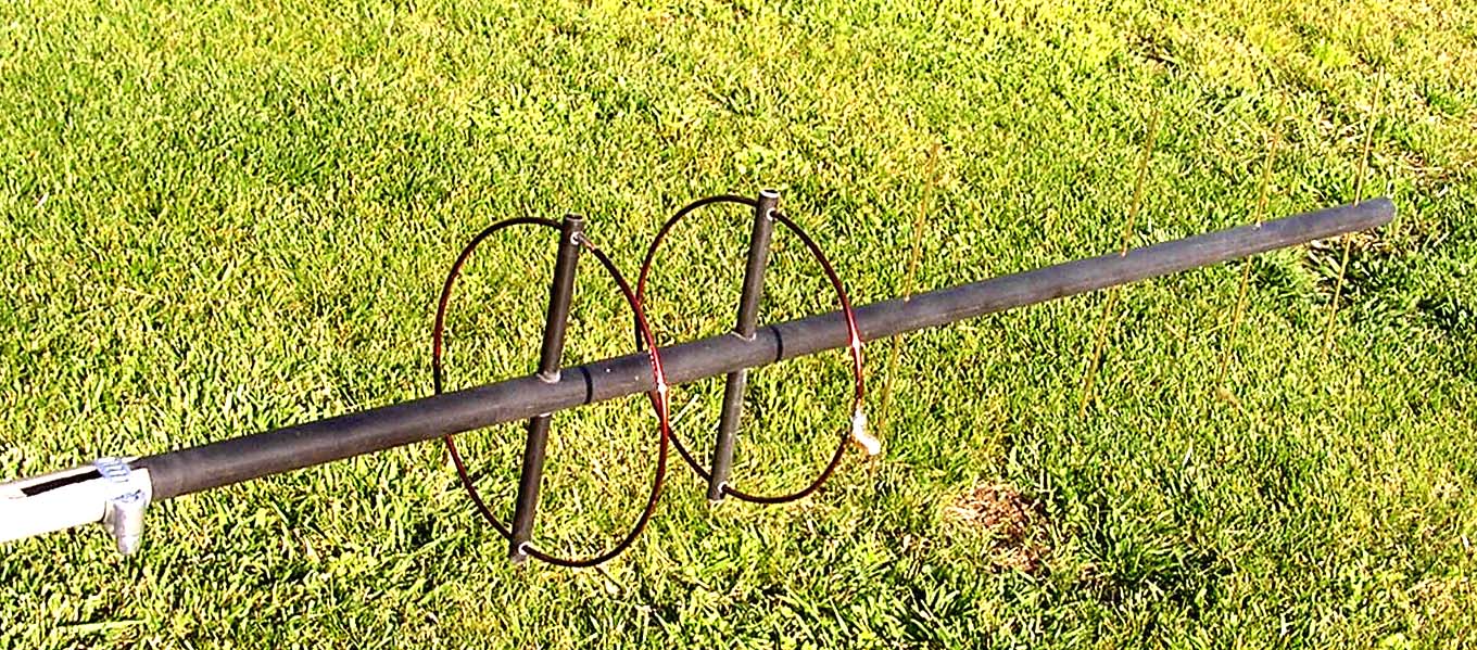
This photo is of a quagi with the same element dimensions, but the boom and supports are made from epoxy tubing and the loops are circular. There is no difference in the performance, but this antenna only weighs about 2 or 3 ounces.

HOME

The reflector is placed at the "0" position on the boom and the other elements are spaced as shown on the table from that reference point.
| ELEMENT | LENGTH | SPACING |
| REFLECTOR LOOP | 13.88 | 0 |
| DRIVEN ELEMENT LOOP | 13.20 | 3.36 |
| DIRECTOR 1 | 5.420 | 6.50 |
| DIRECTOR 2 | 5.365 | 11.40 |
| DIRECTOR 3 | 5.275 | 15.00 |
| DIRECTOR 4 | 5.265 | 18.00 |
The SMA connector has the center pin cut to .10 inch. A longer pin will change the resonant frequency. This antenna has also been made with a 1/2 inch fiberglass boom. Any fiberglass should be coated with epoxy or polyester resin to waterproof it. Number 10 AWG wire could be substituted for the 11 AWG, but the resonant frequency would need to be checked. Smaller loop wire and larger diameter director material will degrade the performance.
This photo is of a quagi with the same element dimensions, but the boom and supports are made from epoxy tubing and the loops are circular. There is no difference in the performance, but this antenna only weighs about 2 or 3 ounces.
