The old 160 meter amplifier had a 4-1000A tube. With only 100 watts of drive, it wasn't possible to get more than 1 KW output. I had a new 3CX1200D7 tube that would easily run 1500 watts output with my 100 watts. When all the parts were collected, the metal box was started.
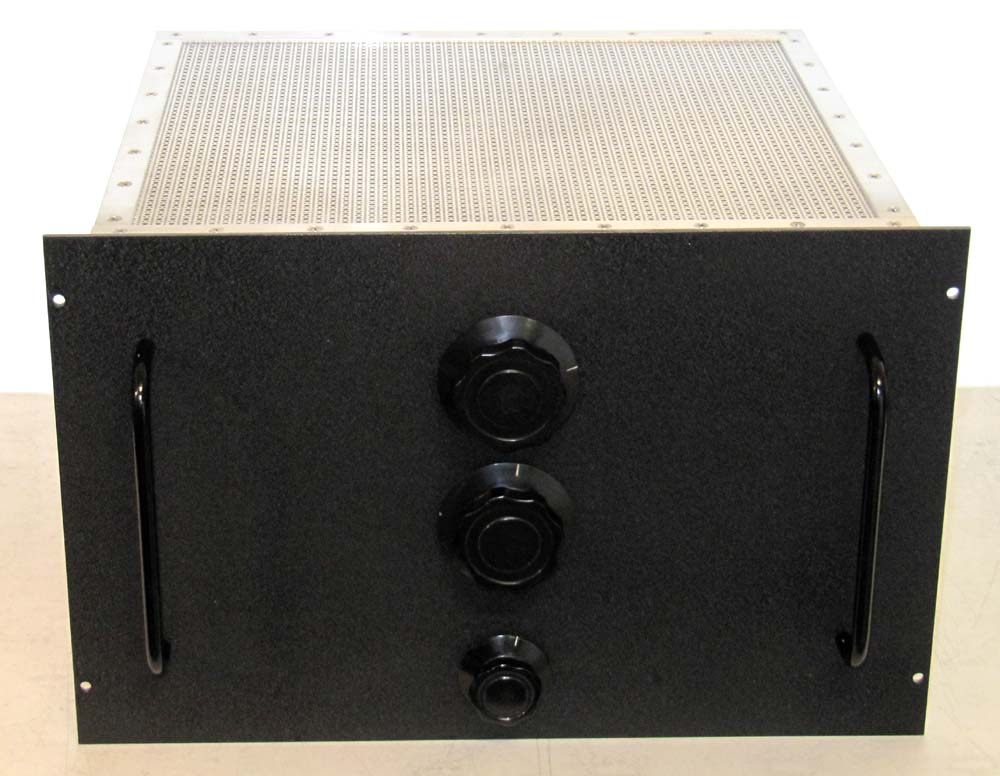
The construction of the box was the same as the other push pull amps. A problem occured when I tried to buy .125 thick 6061 T6 aluminum for the front panel. Clinch studs have been used to attach the box to the panel. The heads of the studs had to be sanded flat before painting. With this amp, I am trying something different. Three sheets of .050 thick aluminum were cut to the size of the final front panel. Two sheets were laminated together using "J-B Weld", a two part epoxy. The studs were placed in this composite sheet. The final sheet was laminated over the stud heads and was easy to paint over. The socket is an Eimac SK-410. The amp can use a 4-1000A if the socket is replaced by an SK-510 with its glass chimney. The filament transformer can be adjusted to either filament voltage.
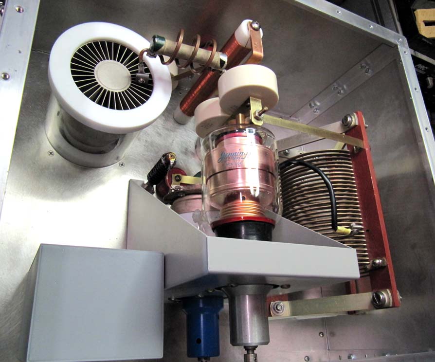
The circuit is the standard PI network with a "Q" of 12. The output circuit uses a large edge wound coil made by Cardwell Condenser. A 500 pf at 10,000 volt vacuum capacitor is used in the input and a 750 pf in the output. A pair of 500 pf mica capacitors are used to pad the output. The 1 mh RF plate choke was wound on 1 inch diameter Delrin that was threaded to space the #24 wire. Two 4800 pf at 20,000 volt transmitting mica capacitors are used as the plate circuit by pass and two more for plate blocking. The 3CX1200D7 is smaller in diameter than the glass 3-500A size tubes I have been cooling with the Coleman lantern glass. To fill in the gap, I turned a half inch thick plate of Teflon to form a cap. The inside diameter just catches the edge of the tube and the outer diameter extends past the glass chimney. A grove in the Teflon fits over the lip of the glass and secures the cap in place. All the air now goes through the anode fins. The Teflon will handle 700 degrees so is in no danger of melting.
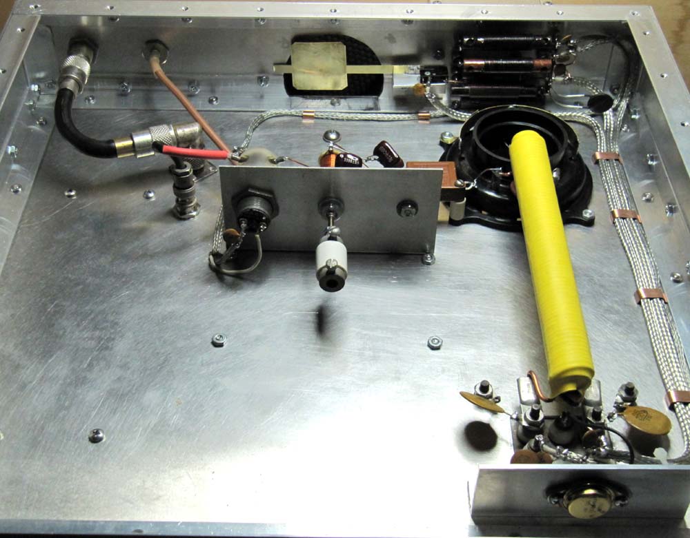
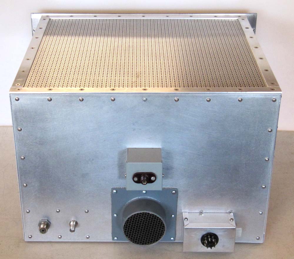
The filament choke is wound on a 5/8 diameter ferrite rod. A 6.8 volt/50 watt zener diode provides bias. All leads are filtered with an RF choke and feed through by-pass capacitor. A thermistor is placed in the filament supply lead to cut the inrush current. The voltage to the filament transformer is also fed through a micro-switch with a wind vane to turn the tube off if the air supply fails. The air enters the amplifier through a honeycomb duct.
Vacuum relays are used for the input and the output. A PI-network with a "Q" of 4 is used to tune the input and is tunable from the front panel.
HOME
The construction of the box was the same as the other push pull amps. A problem occured when I tried to buy .125 thick 6061 T6 aluminum for the front panel. Clinch studs have been used to attach the box to the panel. The heads of the studs had to be sanded flat before painting. With this amp, I am trying something different. Three sheets of .050 thick aluminum were cut to the size of the final front panel. Two sheets were laminated together using "J-B Weld", a two part epoxy. The studs were placed in this composite sheet. The final sheet was laminated over the stud heads and was easy to paint over. The socket is an Eimac SK-410. The amp can use a 4-1000A if the socket is replaced by an SK-510 with its glass chimney. The filament transformer can be adjusted to either filament voltage.
The circuit is the standard PI network with a "Q" of 12. The output circuit uses a large edge wound coil made by Cardwell Condenser. A 500 pf at 10,000 volt vacuum capacitor is used in the input and a 750 pf in the output. A pair of 500 pf mica capacitors are used to pad the output. The 1 mh RF plate choke was wound on 1 inch diameter Delrin that was threaded to space the #24 wire. Two 4800 pf at 20,000 volt transmitting mica capacitors are used as the plate circuit by pass and two more for plate blocking. The 3CX1200D7 is smaller in diameter than the glass 3-500A size tubes I have been cooling with the Coleman lantern glass. To fill in the gap, I turned a half inch thick plate of Teflon to form a cap. The inside diameter just catches the edge of the tube and the outer diameter extends past the glass chimney. A grove in the Teflon fits over the lip of the glass and secures the cap in place. All the air now goes through the anode fins. The Teflon will handle 700 degrees so is in no danger of melting.
The filament choke is wound on a 5/8 diameter ferrite rod. A 6.8 volt/50 watt zener diode provides bias. All leads are filtered with an RF choke and feed through by-pass capacitor. A thermistor is placed in the filament supply lead to cut the inrush current. The voltage to the filament transformer is also fed through a micro-switch with a wind vane to turn the tube off if the air supply fails. The air enters the amplifier through a honeycomb duct.
Vacuum relays are used for the input and the output. A PI-network with a "Q" of 4 is used to tune the input and is tunable from the front panel.